A logic analyser is one of the cheapest and most powerful tools you can use in electronics. It helps you visualize how devices communicate — showing you logic levels, signal timing, and protocol data in a way that’s far more insightful than just reading datasheets.
Although I’ve owned a logic analyzer for a while, I had never used it — until now.
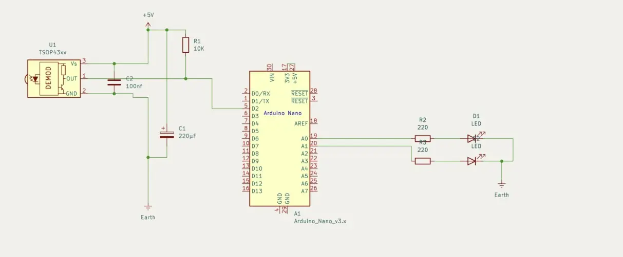
To analyse the IR remote control signals, I built a simple circuit on a breadboard. I’ve also shared the schematic below for reference.
After just a few keystrokes, I noticed that the Chinese remote sends each IR signal at least twice to the receiver.
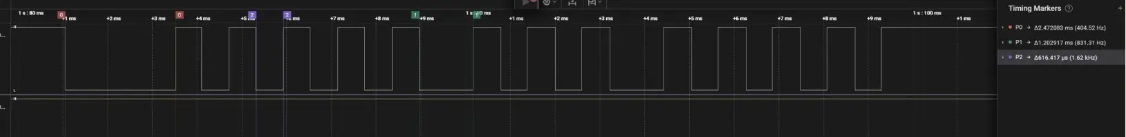
By analyzing the timing with a logic analyzer, I discovered that the remote uses the SIRC protocol. It transmits data at a frequency of 40kHz, following a consistent pattern:
- Start bit: 2.4 ms
- Logic 1: 1.2 ms HIGH + 0.6 ms LOW
- Logic 0: 0.6 ms HIGH + 0.6 ms LOW
It’s important to note that most IR receivers are active LOW, meaning they pull the signal LOW when they detect an IR pulse.
Please checkout the website for more information about SIRC and other IR communication protocols.
Although modern homes often include advanced automation systems like Alexa or Google Home, I decided to go back to basics and write a simple C program to build a SIRC receiver. This receiver toggles relays (or in this case, an LED) based on IR commands—perfect for understanding how things work under the hood.
You can check on my GitHub repo to see 12 bit version of Sony SIRC protocol.
Experiment:
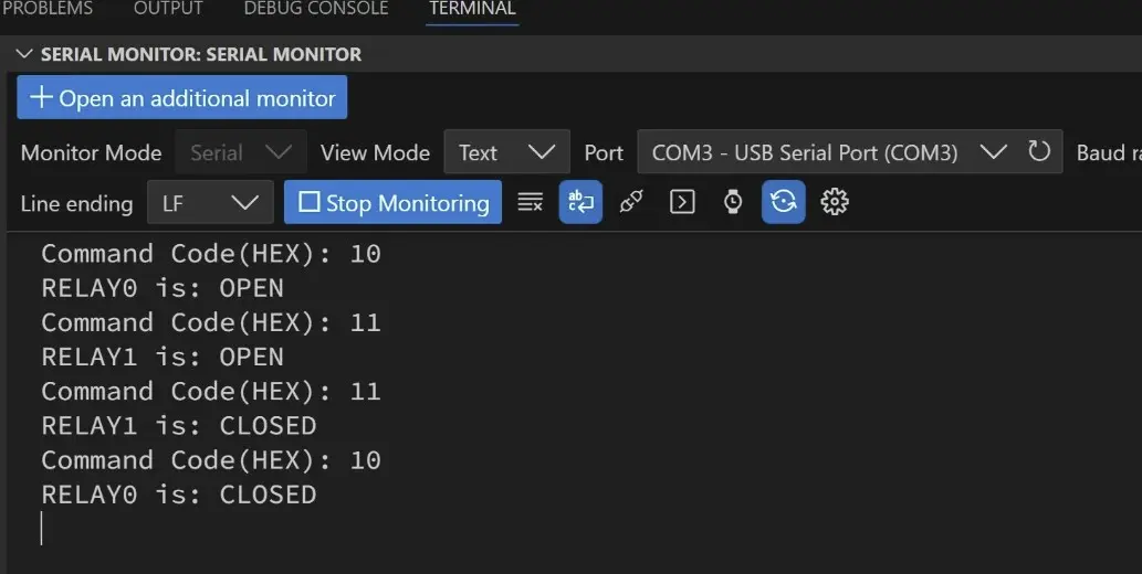
Here is the output of the Serial monitor. Current version of code supports only two keys combination, which are Channel + and Channel -.